
The following lecture notes are adapted from those of Karol Wadolowski (CU EE'19).
ECE 150 Digital Logic Design: Lesson 2
Table of Contents:
Remark
This lecture differs from the previous in that we are interpreting and as boolean values: false and true, not inherently values indicating quantity. We will show that boolean algebra forms a very general framework, and circuits dervied from boolean expressions can be used to implement numerical arithmetic if we choose to interpret circuit inputs and outputs as belonging to the binary number system.
Logic Gates
Logic gates are our tools of binary (True/False, Yes/No) decision making. Given a set of binary inputs, desired outputs can be expressed via a combination of the below fundamental gates.

NOT           OR             AND            XOR            NOR            NAND
-----        -------        -------        -------        -------        -------
A | Z        A B | Z        A B | Z        A B | Z        A B | Z        A B | Z
=====        =======        =======        =======        =======        =======
0 | 1        0 0 | 0        0 0 | 0        0 0 | 0        0 0 | 1        0 0 | 1
1 | 0        0 1 | 1        0 1 | 0        0 1 | 1        0 1 | 0        0 1 | 1
             1 0 | 1        1 0 | 0        1 0 | 1        1 0 | 0        1 0 | 1
             1 1 | 1        1 1 | 1        1 1 | 0        1 1 | 0        1 1 | 0
Each gate has an associated logic symbol and truth-table, and algebraic representation. They represent both mathematical operations and idealized circuit elements.

We call NANDs and NORs universal gates as all others can be built exclusively using either NANDs or NORs. This can have the benefit of simplifying chip design, ensuring equal propagation delay between all gates, or simplying using your entire chip!
Boolean Algebra
Here we introduce how to manipulate and simplify boolean expressions symbolically. We start with our assumed rules (postulates) concerning the NOT, AND, and OR operations.
From these postulates, the following theorems can be derived.
These theorems can be proved easily via truth tables, but it is good excersice to become comfortable with symbolic manipulation for simplifying expressions.
Proofs:
(1)                           (2)
A | A+A       A | AA          A | A+1       A | A0
=========     ========        =========     ========
0 | 0+0=0     0 | 00=0        0 | 0+1=1     0 | 00=0
1 | 1+1=1     1 | 11=1        1 | 1+1=1     1 | 10=0
<=> A+A = A   <=> AA = A      <=> A+1 = 1   <=> A0 = 0
(3a)
(3b)
(4a)
(4b)
(5)
(de Morgan's)
(a)                           (b)
A B | !(A+B) | !A!B           A B | !(AB) | !A+!B
====================          ===================
0 0 |   1    |  1             0 0 |   1   |  1
0 1 |   0    |  0             0 1 |   1   |  1
1 0 |   0    |  0             1 0 |   1   |  1
1 1 |   0    |  0             1 1 |   0   |  0
<=> !(A+B) = !A!B             <=> !(AB) = !A+!B
An easy way to remember de Morgan's theorem is that NOT distributes over (or factors out of) AND/OR by replacing with OR/AND.
With these theorems, we can now simplify the expression from the example circuit above.
Using boolean algebra, we've gone from a 5 gates to 3, and obtained a much more simple expression.
Karnaugh Maps
K-maps are a graphical tool used for boolean expression simplification. The output of a K-map simplification is a sum-of-products expression, i.e. and OR of ANDS, ex. .
K-maps work off the property that and gray-code – enumerating your inputs by only changing one symbol at a time.
To simplify an expression:
create a 2D grid of cells of inputs in rows and columns by gray-code
fill in cells with output values (0/1) or dont-cares (X)
group adjacent 1-cells in largest powers of 2 until all 1s are part of a group. Overlap is fine, and don't-cares can be part of a group. Grouping with wrap-around is possible.
Write output expression as a SOP where each term corresponds to a group, including inputs which do not change within the group.
K-maps are best understood by examples. Here is a primer from the textbook:
Simplify the sum-of-products expression,
using both a K-map, and then again via boolean algebra rules.
solution: first, we can form the truth-table for the expression. This can be done by brute force, or, more easily, by noting that each term in the SOP expression contributes to one-or-more "1s", with the remaining rows being zero.
Once we have a truth-table, forming the K-map is a simple rearrangement. Due to the gray-coding of the K-map, it's useful to do this by labeling which cells correspond to which states. 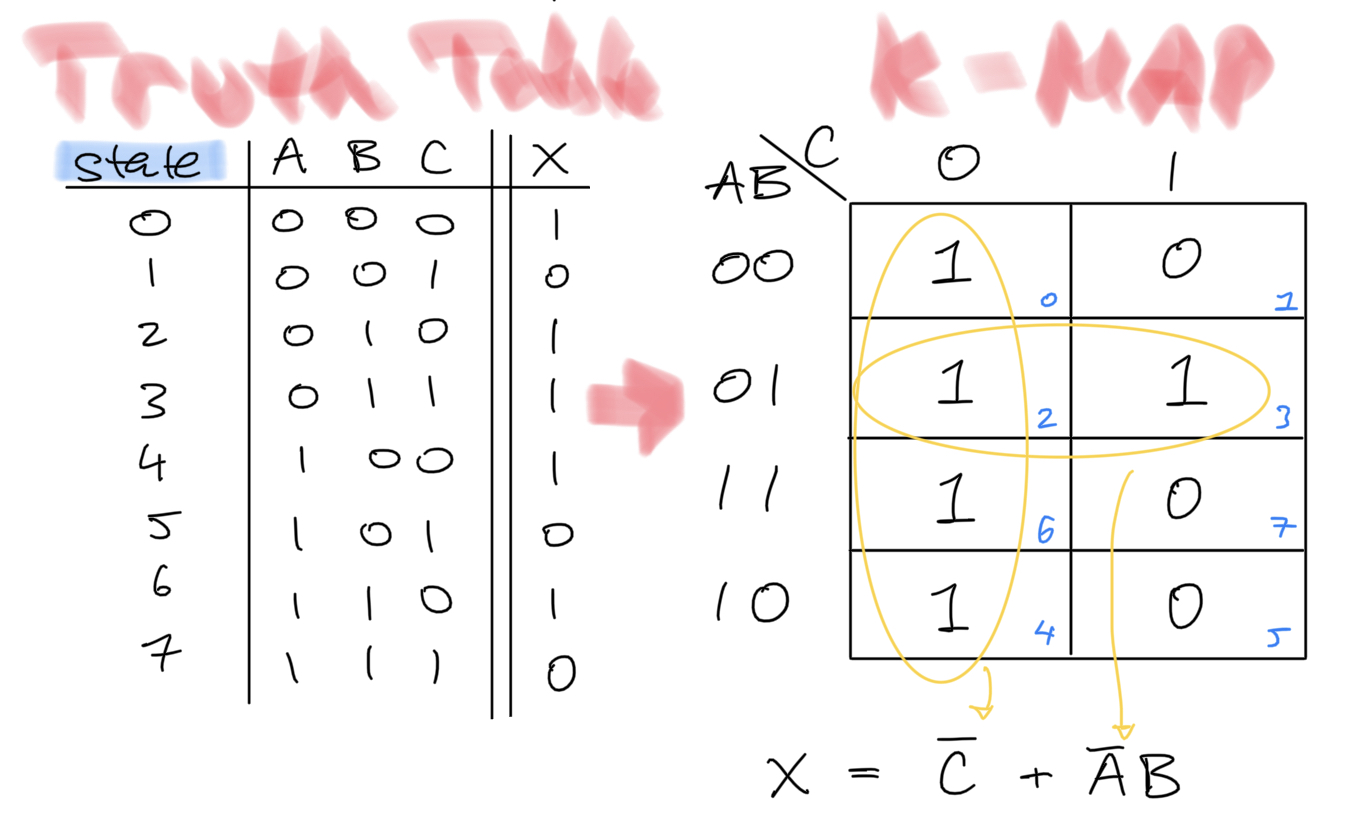
Once the K-map is filled in, we follow the above steps. And group "1s" in the largest powers of 2. The final expression,
is far simplier, as intended.
We now verify that boolean algebra rules achieve the same result:
Clearly, both methods achieve the same results, though K-maps are a powerful graphical tool which may save time and headaches!
The next example illustrates two addtional concepts don't-cares and K-map wrap-around.
A 7-segment display is 7 LEDs arranged to allow easy display of decimal symbols (and other symbols if you're tricky!). Below we show these 7 LEDs indexed, , along with the decimal symbols as we wish to display them. Our goal for this example is to is to obtain simplified boolean expressions for each LED given a 4-bit binary coded decimal (BCD) input, .
Below we show how to obtain expressions for and via K-maps. The remaining LEDs are left as excercises. 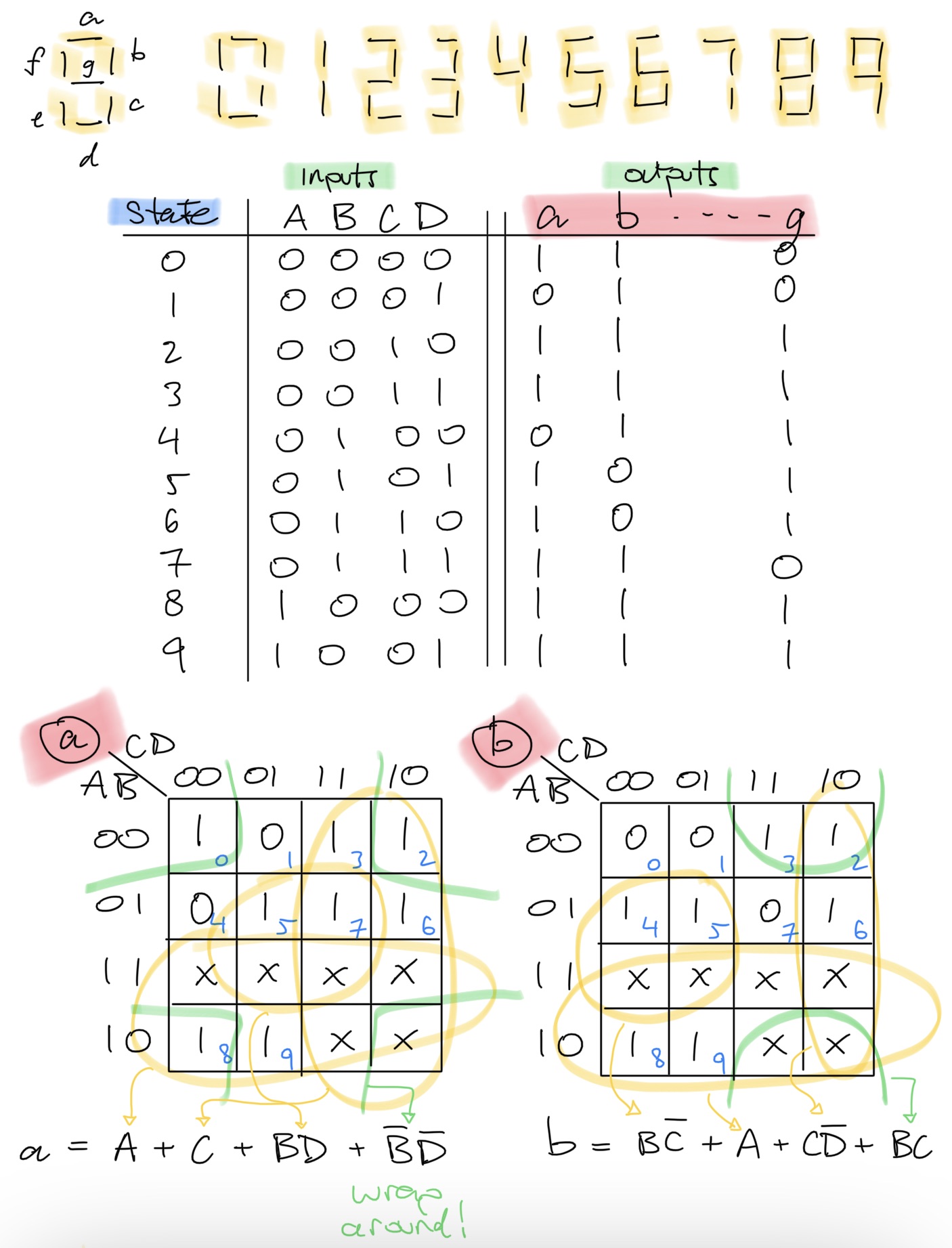
Upon placing the truth-table values for a single output column (ex. or ) into their K-map cells, we notice that not all states are accounted for. For this example, we consider these states invalid, and thus label them as don't-care states. When circling groups in our K-maps, we can include dont-care if it is advantagous in reducing the expression, or we can ignore them if they do not aid in circling "1s".
The gray-coding used simply encodes the property that adjacent cells may only change by one input. The K-map wrap-around property comes from the fact that the first and last rows/columns are only changing by one input, and hence should also be considered as adjacent. Geometrically, you can think of a K-map as a grid on a torus.
Remarks
products-of-sums are the alternative to SOPs. They are equivalent by de Morgan's theorem, but not as intuitive
Combinatorial Circuits
With some familiarty of boolean algebra and logic diagrams, we can understand common combinatorial circuits used throughout digital systems.
Half Adders, Full Adders
Adder circuits perform addition of numbers (e.x. lesson 1). This generally involves interpreting two sets of boolean inputs and as belonging to some number system, and passing them through a set of logic circuits whose output can be interpreted as the sum of those two inputs with respect to the number system.
The most fundamental of these circuits are those of unsigned binary addition, from which addtion for other number systems can be built. Recall, similar to decimal, addition of 2 bits can result in carrying a "1" to the next position. A Half-Adder circuit takes into account this possibility, implementing the following truth table,
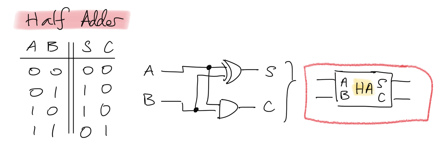
Intermediate symbol positions in addition can not only cause a carry operation but they can recieve a carry symbol. We call a Full-Adder circuit one that is able to both accept and pass on a carry bit, implementing the following truth table. As the name suggests, the full-adder circuit can be implemented via two half-adders.
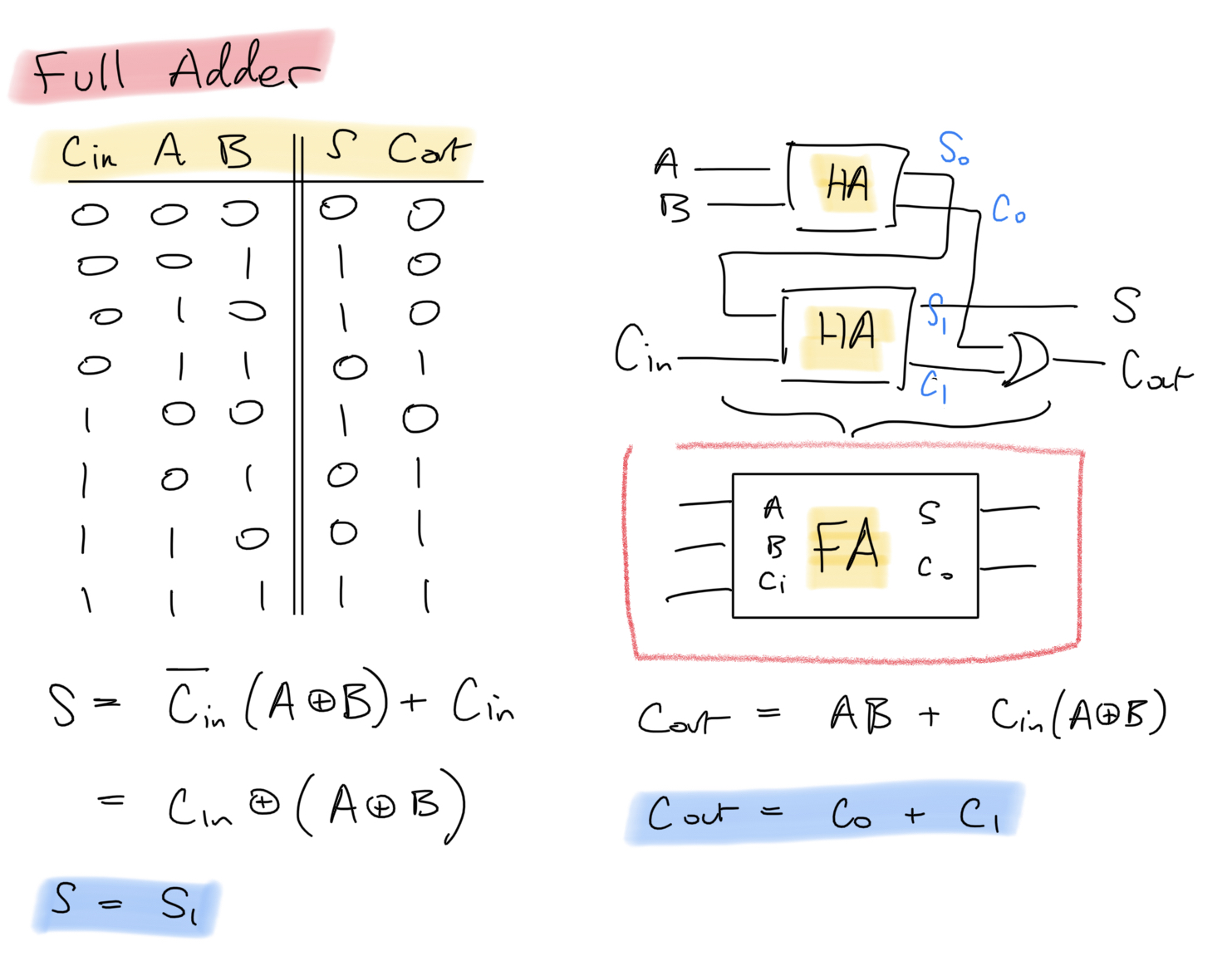
An N-bit Full-Adder circuit, which performs unsigned binary addition of two N-bit binary numbers, can be constructed using full-adder circuits as follows.
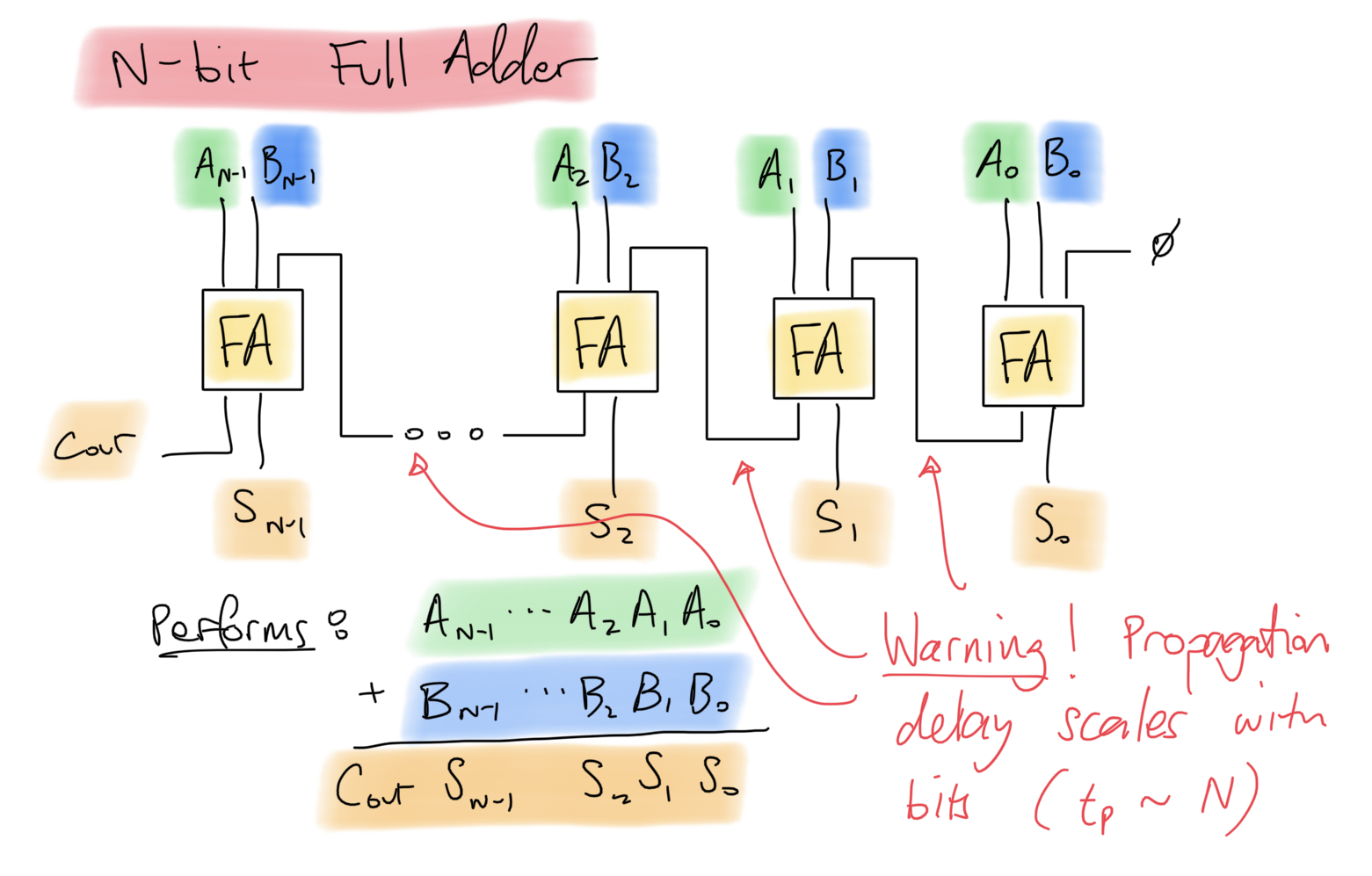
Warning: The above circuit incurs a propagation delay that is proportional to the number of bits in the circuit. This is due to the chaining of carry-out's to carry-in's. A Carry Look-Ahead Adder can reduce this to a constant or logartihmic propagation delay via some extra logic concerning the carry bits.
Multiplexers (Mux/Demux)
(coming soon)
Remarks
Comparators are circuits that take in binary numbers and produce one of three outputs: greater-than, equality, or less-than. As an excercise, derive a boolean expression for this circuit.
Arithmetic Logic Unit (ALU): ALUs are the computational core of CPUs. They are able to perform several different combinatorial operations (addition, subtraction, bit shifting, etc.) in which additional selection inputs decide which of these operations is being used.
References
| [1] | Santa-Clara University ELEN 021 "Postulates and Theorems of Boolean Algebra", 1999. |